Difference between revisions of "Mach-Zehnder Device"
Cmditradmin (talk | contribs) m (→Technique) |
Cmditradmin (talk | contribs) m (→Technique) |
||
| (One intermediate revision by the same user not shown) | |||
| Line 15: | Line 15: | ||
===Technique=== | ===Technique=== | ||
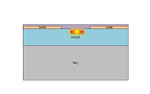
[[Image:Mz5.jpg|thumb|300px|Side view of wave modulator]] | [[Image:Mz5.jpg|thumb|300px|Side view of wave modulator showing light confined to the trench.]] | ||
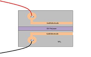
The process for this test device involves etching a channel in a sol-gel layer between two gold electrodes. The channel is then filled with EO polymer. The light is confined to the channel which acts as a waveguide. Standard photolithograpy using masks and etching are used to create the features. | The process for this test device involves etching a channel in a sol-gel layer between two gold electrodes. The channel is then filled with EO polymer. The light is confined to the channel which acts as a waveguide. Standard photolithograpy using masks and etching are used to create the features. | ||
[[Image:Flatcrop.JPG|thumb|300px|Top view of MZ device ]] | [[Image:Flatcrop.JPG|thumb|300px|Top view of MZ device ]] | ||
{{#ev:youtube| | {{#ev:youtube|e0bbH_lnb7Q}} | ||
=== Links === | === Links === | ||
Latest revision as of 08:46, 28 March 2012
| Return to Research Tool Menu |
Overview
The Mach-Zehnder (MZ)device is used to modulate the light passing through a channel by applying an electric current. This technology is widely used in fiber optic communications. New electro-optic polymers can be used in the channel to achieve higher switch speed and lower turn on voltages.
Significance
The MZ devices is based on interference. An incoming wave of light is split into two paths. One path goes through some kind of electro-optical material and then is recombined with the other light path. Small changes in the index of refraction of the electro-optical material controlled by the electric current slightly changes the phase of the light on that path. When it recombines with the original light constructive or destructive interference occurs. <swf width="600" height="200">http://depts.washington.edu/cmditr/media/mz.swf</swf>
Technique
The process for this test device involves etching a channel in a sol-gel layer between two gold electrodes. The channel is then filled with EO polymer. The light is confined to the channel which acts as a waveguide. Standard photolithograpy using masks and etching are used to create the features.

