Second-order NLO Materials
| Previous Topic | Return to Second-order Processes, Materials & Characterization Menu | Next Topic |
Amorphous polymers are desirable materials for several reasons however in order to take full advantage of the EO potential of the polymer embedded chomophores these molecules must be well organized in the bulk material. Poling is the process of bringing chromophores into a desired alignment in a material.
Linear Electro-optic Effect
The polarization density can be written as a Taylor series
- <math>P_{ind} = \chi^{(1)} E_1 + 1/2 \chi^{(2)} E_1 E_2 + 1/6 \chi^{(3)} E_1 E_2 E_3 + ... \,\!</math>
Index of refraction is related to susceptibility (and therefore ultimately back to polarizability) by:
- <math>n^2 = 1 + 4\pi \chi\,\!</math>
Electro-optic effect Consider the case where one field is E1cos[ωt] and second field is a static DC electric field (or very low frequency DC field) of magnitude E2. The second-order term of the induced polarization simply becomes:
- <math>\chi^{(2)} E_1 E_2 cos[\omega t]\,\!</math>
and therefore:
- <math>P = ( \chi^{(1)} + 1/2\chi^{(2)} E_2 ) E_1 [cos \omega t]\,\!</math>
Notice that the the second term χ(2) is field dependent.
Thus, when an electric field is applied to such a poled polymer, the index of refraction of the material will change. This sensitivity of the material to having its index of refraction changed by application of an external electric field is characterized by its so-called electro-optic coefficient, coefficient (r33).
For many years it had been suggested that electro-optic polymers could exhibit large r33 greatly surpassing that of a technologically important crystal, lithium niobate. It is transparent, it is inexpensive, it can be grown in large sheets, and it has an r33 of 30.5 pm/V. This is a reasonable r33 that allows you to build devices. When we build organics we have synthesize new compounds, worry about stability, worry about orientation, and how to keep them poled. But there are a significant advantage to organics.
While there are both electronic and vibrational components to the non-linearity in lithium niobate, a large component is vibrational. This puts an upper limit on the frequency with which that LiNbO3 can be modulated. If a driving field approaches the vibrational frequency then the molecules can not respond quickly to the applied field. The response trails off and there is only the electronic contribution for the non-linearity.
Organic materials are completely dominated by the electronic contributions and therefore can be modulated at very high frequencies.
It is also possible to get organics with an r33 that is much higher (for example 55 pm/V) than LiNbO3. This means that the Vpi (the voltage required for a π phase shift) can be less to get the same change in optical property.
Finally it possible to integrate electronic with optical parts right on a chip. Polymer technology is going to make it much easier to combine these materials on a chip.
In the field of silicon photonics there are waveguides built with ebeam lithography on which the polymer can be spin coated and fill the channels. Organics are amorphous whereas LiNbO3 is a single crystal material which makes it very challenging to apply to chip-scale device.
NLO materials in EO-Modulators
An electrode is located on either side of the light path which passes through an electro optical material. An opposite field can be applied to each path slowing the light on one side and speeding the light on the other. There are many factors that contribute to the figure of merit Vpi (the voltage that is required to shift the wave one half of a wavelength). A longer optical wavelength is better. A long interaction length gives more time for the material to respond to the field, but this means the optical material must be very clear so that optical intensity is not lost. Light intensity can be lost by absorption, diffraction and scattering. The 1.31 microns and 1.55 microns are popular telecommunication wavelengths because they are easily propagated through optical fiber. This is the typical wavelength that the modulators need to work with. Many NLO materials absorb in the 650- 750 nm range. 640 nm is about 2 eV (1ev = 1240/ wavelength nm); 1.55 microns is about .8 eV. A lot of the molecules are absorbing at about 700nm (1.7 eV). The absorption tail of a molecule can go out a long ways. At some point you have to worry about C-H bonds because of overtones due the C-H stretching frequency that occur at 3000 cm-1 (3333 nm). This means there could be some absorption at 1600 nm (1/2 of 3333 nm) due to C-H overtones. This is a problem.
Another problem is that the high concentrations of chromophores in these systems results in chromophore-chromophore interactions, inhomogeneities of the chromophore concentrations, and chromophore polymer interactions. Each of these factors leads to a variation of the refractive index which can lead to the scattering of light at some level. If the interaction length of the light in the Mach Zehnder devices needs to be long then it is important to keep the scattering in the organic component to a minimum.
It is important to have a high index of refraction and high electro-optic coefficient. Index of refraction relates to dielectric constant which relates to susceptibility, which relates to polarizability (α), which relates to the transition dipole moment within the context of a two level model. Change of dipole of moment is the state dipole moment for the excited state minus the state dipole moment for the ground state. Transition dipole moment is an integral of the complex conjugate of the excited state wavefunction, the transition dipole moment operator (which scales like R) and the ground state wave function Dτ. The transition dipole moment relates to the oscillator strength (the area under the absorption curve) which is related to the extinction coefficient. Organic dyes that are used in second order NLO systems are materials that have a high refractive index and strong low energy absorptions.
Poling of Chromophores in Polymers
In order to achieve a high electro-optic coefficient you start with molecules with a high first hyperpolarizability (beta), and then get those molecules oriented in the same direction. (For now we will examine orientation for high EO coefficient and will ignore the orientation required for second harmonic generation which require a different orientation)
Orientation can be achieved with crystalline materials. The Marder group was able to develop crystals of DAST. (They were working with a Japanese group at the same time who succeeded in making a crystal of the hydrate of the material due to their high local humidity. Marder’s group in California was able to make the DAST crystal due to the low local humidity. One crystal was centro symmetric and one was non-centrosymmetric.) Growing crystals is very difficult. Another group spent 10 years developing the method to grow one crystal. (Rainbow Photonics)
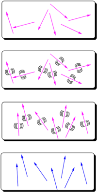
The most widely used method for aligning molecules is the poled polymer method. Recall that dipole moment is a vector, and first hyperpolarizability beta is a tensor. Assume that the molecule has one axis (the long axis) along which the hyperpolarizability beta dominates. If the dipole moment is aligned along the long axis then an applied electric field will cause a torque to reorient the molecules. (Boltzman will be working against this attempting to randomize the orientation) There will be a distribution of orientations but if you sum over all the vectors there will be a net orientation. This in turn aligns the hyperpolarizability tensor. In the limiting case in which the hyperpolarizability is perpendicular to the dipole moment there will be an alignment of the hyperpolarizability tensor in a plane but within that plane the tensors will be oriented at all angles. This results in a zero overall second order optical activity. Therefore we need molecules with large dipole moments that are oriented along the same axis as the hyperpolarizability tensor.
- Assume you are start with molecules that have high nonlinearities but they are arranged in a random orientation. An NLO chromophore with a dipole moment (such as paranitroaniline) and a glassy polymer are dissolved in an organic solvent and spin-coated onto a substrate. The film is then heated above or around its glass transition temperature (Tg). The glass transition temperature at which there is free motion of the main chain of the polymer.
- At this temperature, the molecules can rotate in the rubbery matrix. An intense DC electric field as high as 106 V/cm is applied and this field creates a force on the dipole moments of the chromophores, aligning them.
- Thus, the polymers and chromophores must be nonconducting to support these large fields. With the electric field still applied, the film is cooled below the Tg of the polymer, restricting the motions of the chromophores.
In this manner you can produce a material that has a second order nonlinear optical effect using molecules that have a second order nonlinear optical effect.
The resulting noncentrosymmetric structure contains the molecular units oriented on the average normal to the film (C∞v symmetry). In this state, the electric field of an optical beam propagating through the film can be maximally modified when the field is parallel to the orientated molecular units.
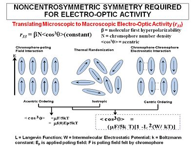
The goal of "poling" is to get all the chromophores to orient the same direction in a macroscopic sample. There are several ways to do this. We can place the chomophore in a host matrix like a commercial polymer, heat it up to the glass transition temperature, and apply an electric field. The dielectric moment of the chromophore interacting with the field will cause some ordering.
The order parameter will be the dipole moment interaction divided by the 5 times the thermal energy.
The magnitude of the second-order NLO effect in a poled polymer film is related to several factors.
Using a non-interacting oriented molecular gas model, the follow equation has been derived to describe the second-order susceptibility in the direction of the poling field (χ (2)333). It is calculated:
- <math>\Chi^{(2)}_Template:333 = N F \beta_{\mu} <cos^3\theta>\,\!</math>
Where:
- <math>N\,\!</math> is the number density of the chromophores in the material
- <math>F\,\!</math> is a constant
- <math>\beta _mu\,\!</math> is the component of beta that is aligned along the axis of the dipole moment (eg not 90degrees)
and where:
- <math><cos^3 \theta> = \mu_z E_p /cKT\,\!</math>
- <math>\mu_z\,\!</math> is the dipole moment of the molecule (the larger the dipole, the more it will respond to the field)
- <math>E_p\,\!</math> is the strength of the applied electric field
- <math>k\,\!</math> is the Boltzman constant, T is temperature in Kelvin
- <math>c\,\!</math> is a system dependent factor equal to 5 for isotropic systems, and 1 for ideal liquid crystalline systems (Ising systems)
In liquid crystals the orientation of one molecule can affect neighboring molecules (cooperativity) <cos3θ> is the induced polar order which is an average angular orientation where theta is the angle between the poling axis and the molecular dipole moment of the chromophores. Molecules with large dipole moments will tend to repel and that interferes with poling especially when they get too close (high concentration).
This equation is valid a low field, :<math>\mu_zE_p < kT\,\!</math>.
When there is centric ordering
- <math><cos^2 \theta > = (\mu F/5kT) [1- L^2(W/kT)]\,\!</math>
where:
- <math>W\,\!</math> is the intermolecular electrostatic potential
- <math>L\,\!</math> is the Langevin function
- <math>F\,\!</math> is the poling field felt by the chromophore
Key Molecular Properties for Poled Polymers
- large optical nonlinearities (large χ(2) - large r33)leading to low drive voltages.
- thermal stability - high temperatures in fabrication (want to pole 150 - 200°C above Tg) and high operating temperatures –very few organic dyes are are stable above 250°C- molecules can be engineered to remove weak points.
- photochemical stability - materials undergo intensive irradiation during applications
- stable against oxidation- and reduction processes due to high electrical fields in fabrication and exposure to air (oxygen)
- minimized self aggregation - aggregation causes scattering loss and aggregation makes molecules harder to orient - mitigated by covalent linkage to polymer-backbone
- long-term orientational stability of devices- for devices that are deployed in telecommunication (underground) they should last at least 75 years.
Schematic of Poled Polymers Strategies
The poled orientation is thermodynamically unstable and therefore the orientation quickly decays in low Tg polymers such as poly(methylmethacrylate), resulting in a greatly reduced nonlinearity. The diagram show several strategies for linking chromophores to polymers so they are more constrained.
The motion of chromophores in polymer matrices might be further restricted if the chromophore is covalently attached at one or more sites to the polymer. One end of the chromophore is pinned down it may more thermally stable. This also reduces the tendency for the polymer and chromophore to separate into phases because they are essentially glued together.
Accordingly, several groups have explored covalently attached chromophores to polyimides either in the main chain or as a side chain. This approach can lead to polymers with exceptional thermal stability. Lately, Jen's group has reported a 2-step synthesis for NLO side-chain aromatic polyimides. The advantages of this procedure include the ease in controlling the loading level of the chromophore and adjusting the polymer backbone rigidity.
Theoretical Methods for Improving NLO activity
An important aspect of research and development is connecting fundamental science to applied technology. Theoretical methods allow us to predict the NLO activity of materials and to rationally design materials that will have desired properties.
quantum mechanical calculations
Quantum mechanics has helped improve non-linear optical activity (NLO). The molecular first hyperpolarizability, that is, the charge re-distribution you get from the application of an electric field, has gone up exponentially over the recent years. This improvement is even greater than Moore’s law. In addition statistical mechanics has help improve the macroscopic EO activity.
<math>r_{33} = \beta(\epsilon,\omega)N<cos^3\theta>\,\!</math>
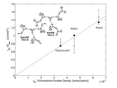
The electro-optic cofficient r33 is determined by the molecular property first hyperpolarizability <math>\beta(\epsilon,\omega)\,\!</math> and a number density. So for the maximum effect all the molecules must be lined up in the same direction. You can use quantum mechanics to optimize the first part (hyperpolarizability), and statistical mechanics to optimize the second part (number density), and have a feedback loop between the two approaches.
Density Functional Theory
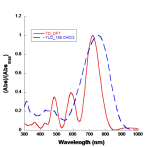
Density Functional Theory (DFT) resulted in a Nobel Prize in physics in 2000. Basically you are replacing a wave function computation with a density. Density is <math>\Psi \psi*\,\!</math> the product of two wave functions. That has some computational speed advantages. But the major advance is Real Time Time Dependent Density Functional Theory (RT-DFT). This gives you a mechanism for incorporating time dependent phenomenon like applied radiation fields, optical fields, and internal fluctuation of charge fields.
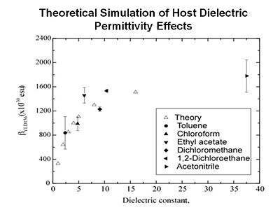
For example, when you place a chromophore in a host material the host is typically a dielectric and it will exert an electric field on the chromophore. You want to be able to take both of these into account. The end result is that you are getting quantitative simulation of linear and non-linear optical properties.
Statistical mechanical calculations
Statistical mechanics has allowed us to get a pretty good understanding of experimental data shown here by diamonds. This is the theoretical prediction. You can also get an analytical expression to tell us where the maximum will occur. More importantly it s given us methods such as shape engineering. Notice that if we go from a prolate ellipsoid shape to a spherical structure the EO activity maxium value can be improved. This has been experimentally observed.
Coarse and fine models
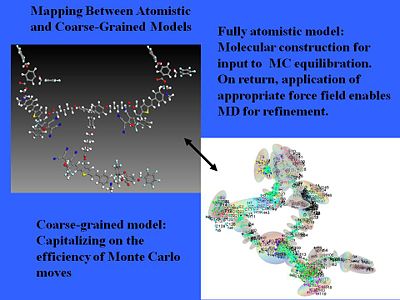
We can even treat more complicated structures. We can use pseudo atomistic Monte Carlo calculations that treat anything that has high conjugation without internal motion as more or less a rigid object and then you correct electron distribution over that object. That will simplify a normal fully atomistic calculation. A chemical model becomes an electrostatic surface.
The beauty of this is that it gives you that it gives you a quantitative prediction of EO activity.
Conclusion
The combination of new QM and SM methods permits quantitative prediction of macroscopic electro-optic activity--Yes, we really do need “Numbers”!
- Previous analysis has tended neglect dielectric effects, to over estimate acentric order and underestimate molecular first hyperpolarizability.
- Laser-assisted electric field poling can be used to improve acentric order.
- Binary chromophore organic glasses permit significant improvement in both electro-optic activity and optical transparency.
- Electro-optic activity of 1000 pm/V (2 orders of magnitude improvement) with optical loss of 2 dB/cm is possible by theoretically-inspired design. This is starting to approach the value of liquid crystals but with a factor of 1011 improvement in processing speed.
| Previous Topic | Return to Second-order Processes, Materials & Characterization Menu | Next Topic |

