Difference between revisions of "Physics of Solar Cells"
| Line 23: | Line 23: | ||
<br clear='all'> | <br clear='all'> | ||
[[Image:opv_power_FF.JPG|thumb|400px|]] | [[Image:opv_power_FF.JPG|thumb|400px|]] | ||
The photocurrent is referred to as the short circuit photocurrent, J<sub>sc</sub>, because there is a current without any external applied voltage. It is as if there was a short circuit in the system. The photocurrent is actually a reverse bias current because electrons flow toward the cathode and the holes flow to the anode. If you start applying a voltage, a forward bias, it will start compensating for that reverse photocurrent and eventually, you will reach point where the current goes to zero. At this point, it is referred to as an open-circuit voltage V<sub>oc</sub> because even with applying a voltage, there is no current. It is as if the system or the electric circuit is open. In the dark, the system works as a normal diode: it has a forward bias after a given threshold and creates a large current, while a reverse bias gives negligible current. Now assume that you shine light but don’t apply any potential. As the light is shined, photons will be absorbed and disassociated at the interface. With the built in potential, the electrons will flow to the cathode and the holes will flow to the anode and thus, a photocurrent that corresponds to a reverse current will be produced. Afterward, a forward bias will be applied at (0, 0) on the graph, just as the dark curve starts to gain a slope. This will generate a current in the opposite direction with respect to the photocurrent and will compensate it. At some point, your current will reach zero as the voltage axis is crossed. | The photocurrent is referred to as the short circuit photocurrent, J<sub>sc</sub>, because there is a current without any external applied voltage. It is as if there was a short circuit in the system. The photocurrent is actually a reverse bias current because electrons flow toward the cathode and the holes flow to the anode. If you start applying a voltage, a forward bias, it will start compensating for that reverse photocurrent and eventually, you will reach point where the current goes to zero. At this point, it is referred to as an open-circuit voltage V<sub>oc</sub> because even with applying a voltage, there is no current. It is as if the system or the electric circuit is open. In the dark, the system works as a normal diode: it has a forward bias after a given threshold and creates a large current, while a reverse bias gives negligible current. | ||
Now assume that you shine light but don’t apply any potential. As the light is shined, photons will be absorbed and disassociated at the interface. With the built in potential, the electrons will flow to the cathode and the holes will flow to the anode and thus, a photocurrent that corresponds to a reverse current will be produced. Afterward, a forward bias will be applied at (0, 0) on the graph, just as the dark curve starts to gain a slope. This will generate a current in the opposite direction with respect to the photocurrent and will compensate it. At some point, your current will reach zero as the voltage axis is crossed. | |||
<br clear='all'> | <br clear='all'> | ||
Revision as of 08:22, 2 June 2009
| Previous Topic | Return to OPV Menu | Next Topic |
Current vs voltage Plot
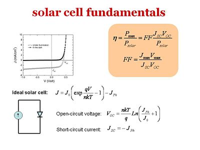
In the dark the basic solar cell structure with the donor component, acceptor component, anode and cathode is a diode. It is represented by the darker curve on the graph
The graph shows a “current density vs. voltage” plot. Electrons and holes are injected in a certain way based on whether a forward bias or a reverse bias is to be achieved. In a reverse bias, where the electrons go from the anode to the cathode, there will hardly be any current. In order for electrons to go from the anode to the cathode, the electrons must jump to the LUMO of the donor component. This will be very high in energy. On the other hand, in a forward bias where the electrons go from the cathode to the anode, there will be an injection barrier. Only when the injection barrier is overcome can your current start flowing. The dark curve is a typical current vs. volt plot for a diode. A reverse bias will produce very little or negligible current and a forward bias will produce a very large current after a threshold. The other lighter curve beneath the dark curve shows what happens under illumination. Under illumination, photons are absorbed in the donor component. If they disassociate at the interface due to the built in potential, the electron will go toward the cathode and the hole will go towards the anode and you will have a reverse current also called a photocurrent. Although an external voltage is not applied, under illumination a photocurrent can result.
Short Circuit Current and Open Circuit Voltage
The photocurrent is referred to as the short circuit photocurrent, Jsc, because there is a current without any external applied voltage. It is as if there was a short circuit in the system. The photocurrent is actually a reverse bias current because electrons flow toward the cathode and the holes flow to the anode. If you start applying a voltage, a forward bias, it will start compensating for that reverse photocurrent and eventually, you will reach point where the current goes to zero. At this point, it is referred to as an open-circuit voltage Voc because even with applying a voltage, there is no current. It is as if the system or the electric circuit is open. In the dark, the system works as a normal diode: it has a forward bias after a given threshold and creates a large current, while a reverse bias gives negligible current.
Now assume that you shine light but don’t apply any potential. As the light is shined, photons will be absorbed and disassociated at the interface. With the built in potential, the electrons will flow to the cathode and the holes will flow to the anode and thus, a photocurrent that corresponds to a reverse current will be produced. Afterward, a forward bias will be applied at (0, 0) on the graph, just as the dark curve starts to gain a slope. This will generate a current in the opposite direction with respect to the photocurrent and will compensate it. At some point, your current will reach zero as the voltage axis is crossed.
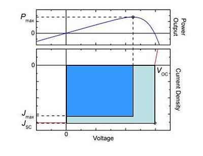
In the lower right quadrant shows a forward bias with positive voltages and negative currents, since the photocurrent is a reverse current. The product of the current and the voltage, J times V, is power. There is a product of the current and voltage that produce the maximum power. The maximum power that can be obtained is found by looking at the dashed backward-L line. If the diode system were ideal, the photocurrent will be the flat up to the Voc and then shoot up vertically. Overall, the product of Jsc and Voc will give the ideal maximized power that can be achieved in the solar cell.
Fill Factor
In the literature, you will people talking about the fill factor (FF) which provides an easy comparison for the performance of a cell compared to the theoretical maximum. Fill factor can be calculated as follows.
- <math>n=\frac {P_{max}} {P_{solar}} = FF \frac {J_{SC} V_{OC} }{P_{solar}}\,\!</math>
- <math>FF=\frac{J_{MAX} V_{MAX} } {J_{SC} V_{OC} }\,\!</math>
where:
- <math>J_{SC}\,\!</math> is the short circuit current
- <math>V_{OC}\,\!</math> is the open circuit voltage
- <math>J_{MAX}\,\!</math> is the maximum current
- <math>V_{MAX}\,\!</math> is the maximum voltage
The fill factor FF is simply the ratio of the area in the blue rectangle with respect to the pale blue rectangle shown on the graph. You want to have a fill factor as large as possible. But often, the fill factor will end up being around 40-60%. In the most efficient cases, it is possible to reach up to 80-85%. Remember that the power efficiency of the solar cell is the output power (Pmax) over the input power (Psolar). It can also be expressed in terms of the fill factor: the power efficiency of the solar cell is equal to the product of the fill factor times the short circuit current Jsc times the open circuit voltage Voc over the input power Psolar. This is an expression that will often come up literature when people discuss solar cells. The goal is to maximize the fill factor, the open circuit voltage, and the short circuit current. You would want the photocurrent as large as possible. The open circuit voltage is actually a measure of the work that can be done by the generated electrical current. The more work done by the current, the more power that was generated.
| Previous Topic | Return to OPV Menu | Next Topic |

