Second-order Processes
| Return to Second-order Processes Menu | Next Topic |
Concept Map for Second Order Non linear Optics
Second order non linear optics involves the search for materials whose optical properties can be controlled with an applied electrical or optical field. They are second order because the effect is quadratic with respect to field strength. These extremely fast processes can be used for optical switching in telecommunication and the frequency effects can be used for specialized spectroscopy, imaging and scanning.
Electro optical materials
EO Materials have a voltage-controlled index of refraction.
Light has a known speed in a vacuum. But when enters a material it slows down. Light has an electrical and a magnetic component. The electrical component will interact with the charge distribution of the atom in the material is passed through. The interaction will slow the light down.
The index of refraction = speed of light in vacuum / speed of light in material.
An electro-optic material (in a device) permits electrical and optical signals to “talk” to each other through an “easily perturbed” electron distribution in the material. A low frequency (DC to 200 GHz) electric field (e.g., a television [analog] or computer [digital] signal) is used to perturb the electron distribution (e.g., p-electrons of an organic chromophore) and that perturbation alters the speed of light passing through the material as the electric field component of light (photons) interacts with the perturbed charge distribution.
Because the speed of light is altered by the application of a control voltage, electro-optic materials can be described as materials with a voltage-controlled index of refraction.
For example, you apply and electric field that alters the charge distribution of the material, which in turn influences the propagation of light through the material. (Pockels effect). The reverse process is called optical rectification. When there are two fields involved this is called a second-order nonlinear optical effect.
<swf width="500" height="400">http://depts.washington.edu/cmditr/media/eo_lightspeed.swf</swf>
In this Flash animation a light source emits photons which travel through the material at the speed of light. When there is no field the electro-optic material has no induced electron asymmetry. Click the battery to add an electric field. The EO materials change their electron distribution which changes their index of refraction so as to slow down light moving through the EO polymer. If these two light beams recombined their wave behavior might interfere. It is this property that can be used to modulate light.
Types of EO materials.
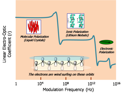
The response speed of EO materials relates to the mass of the entity that is moved.
Liquid Crystals -In liquid crystalline materials there is a change in molecular orientation, which changes the dipole moment and charge distribution of the material, which is turn changes the velocity of light moving through the material. This can be measured by the retardation of the speed of light measure in picometers per volt applied. This is a large effect (>10,000 picometers (pm)/V) but rather slow (103 -106 sec) because we are moving a lot of mass. This is not so useful for high speed communication.
Inorganic crystals the electric field causes ion displacement. This is a small effect (30pm/V) but faster (10-10 sec) because a smaller ion with less mass is moving.
electron chromophore polymer- A third technique uses π electron chromophore containing polymers and dendrimers. An applied electric field can change their π electron distribution. This has a large EO activity (>500 pm/v) and very fast into the terahertz (thz) region (10-14 sec).
Organic EO materials have the potential for faster response, lower drive voltage, larger bandwidth, lighter weight and lower cost. They can also be tailored to specific applications and integrated at the chip scale level.
Polarization Effects
NLO Chromophore
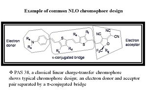
The basic unit of organic electro-optics is the EO-active material, or chromophore.
This chromophore can be thought of as a molecular oscillator interacting with EM radiation.
Electron donor and acceptor moieties are connected by a π -conjugated bridge that serves as a conduit for electron density.
Asymmetric Polarization
In second order non linear optics we are concerned with asymmetric polarization of light absorbing molecules in a material.
This diagram is a representation of what happens to a molecule that is asymmetric when an electric field is applied. A molecule with a dipole, such as 4-nitroaniline, has a charge distribution that leads to a dipole. One side is a donor (d) and an acceptor (a) with a π conjugated system. The magnitude of the induced dipole will be greatest when the electric field is aligned so as to move the electron density towards the electron donor end of the molecule. In a symmetric molecule is there a linear polarizability shown as the straight line. The greater the charge, the greater the induced dipole. In an asymmetric material there a nonlinear effect which makes it easier to polarize in one direction than the other, and increasing electric field has an exponentially increasing effect.
In the presence of an oscillating electric field a linear material will have an induced dipole that is in phase and has the same frequency as the applied field.
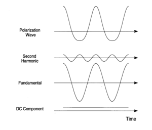
The application of a symmetric field (i.e. the electric field associated with the light wave) to the electrons in an anharmonic potential leads to an asymmetric polarization response. This polarization wave has flatted troughs (diminished maxima) in one direction and sharper and higher peaks (accentuated maxima) in the opposite direction, with respect to a normal sine wave.
It is possible to find the sum of waves that would result in such a wave using techniques such as fourier transform. In the case of a symmetric polarization it is simply the sine wave of the applied field.
This asymmetric polarization can be Fourier decomposed (deconvolved) into a static DC polarization component with components at the fundamental frequency superimposed with a second harmonic frequency (at twice the fundamental frequency). This is a consequence of the material having second order non-linear properties.
As a consequence if you shine a laser at a non-linear optical material you can get light out of a different wavelength than the exciting source. In addition this emission can occur at a wavelength where the molecule is completely non-absorbing. This emission is not due to absorption / fluorescence. In second harmonic generation the light coming out can be twice frequency of the exciting source and the phenomena is tunable.
A laser of one frequency can be used to generate light of other frequencies. For example green light from a neodymium YAG laser (1064nm wavelength - green) can be directed on a non-linear optical crystal such as potassium dihydrogen phosphate and generate a second harmonic which is then used as a source for other experiments.
Since only the time averaged asymmetrically induced polarization leads to second-order NLO effects, only molecules and materials lacking a center of symmetry possess them.
<swf width="500" height="400">http://depts.washington.edu/cmditr/media/07 Assymetric Polarization.swf</swf>
Fourier Analysis of Asymmetric Polarization Wave
Expression for Microscopic Nonlinear Polarizabilities
The linear polarizability is the first derivative of the dipole moment with respect to electric field. In non-linear optical effects the plot of induced polarization vs applied field can be corrected using higher corrections with a Taylor series expansion, including the second derivative of the dipole moment with respect to electric field times the field squared with a single electric field, or higher order terms using the third derivative of dipole moment vs field the field cubed. Μ is the total dipole moment in the molecule which is a sum of the static dipole plus several field dependent term.
- <math>\mu = \mu_0 + (\partial \mu_i / \partial E_j)_{E_0}E_j \quad + \quad 1/2 (\partial^2 \mu_i / \partial E_jE_k)_{E_0} E_jE_k \quad+ \quad 1/6(\partial^3\mu_i / \partial E_jE_kE_j)_{E_0} E_jE_kE_j\,\!</math>
Where
- <math>\mu\,\!</math> is the microscopic nonlinear polarizability
- <math>E_i E_k E_j\,\!</math> are the electric field (vectors)
- <math>\mu = \mu_0 \quad+\quad \alpha_{ij}E_j \quad+\quad \beta _{ijk}/ 2 E E \quad+\quad \gamma_{ijkl} / 6 E E E + ...\,\!</math>
Where:
- <math>\alpha\,\!</math> is linear polarizability
- <math>\beta\,\!</math> is the first hyperpolarizability ( a third rank tensor with 27 permutations although some are degenerate)
- <math>\gamma\,\!</math> is the second hyperpolarizability, responsible for third order non linear optics.
The terms beyond αE are not linear (they have exponential terms) in E and are therefore referred to as the nonlinear polarization and give rise to nonlinear optical effects. Note that Ej, Ek, and Ej are vectors representing the direction of the polarization of the applied field with respect to the molecular coordinate frame. Molecules are asymmetric have different polarizabilities depending the direction of the applied electric field.
Alpha is the second derivative of the dipole moment with respect to field, and is also the first derivative of the polarizability with respect to field. Beta is the first derivative of polarizability with respect to field, and gamma is the first derivative of the first hyperpolarizability with respect to field.
Nonlinear polarization becomes more important with increasing field strength, since it scales with higher powers of the field (quadratic or cubic relationships). Second harmonic generation was not observed until 1961 after the advent of the laser. Under normal conditions,
- <math>\alpha_{ij}E \quad > \quad \beta_{ijk}/2 E·E \quad > \quad \gamma_{ijkl} /6 E·E·E.\,\!</math>
Thus, there were few observations of NLO effects with normal light before the invention of the laser with its associated large electric fields.
With very large electric fields there can be dielectric breakdown of the material.
The observed bulk polarization density is given by an expression analogous to (7):
- <math>P = P_o + \chi^{(1)} ·E + \chi^{(2)}·· EE + \chi^{(3)}···EEE+ ...\,\!</math> (8)
where the :<math>\chi^{(i)}\,\!</math> susceptibility coefficients are tensors of order i+1 (e.g., :<math>\chi^{(2)}_{ijk}\,\!</math>). Po is the intrinsic static dipole moment density of the sample.
The linear polarizability is the ability to polarize a molecule, the linear susceptibility is bulk polarization density in a materials which has to do with the polarizability of the molecules and the density of those molecules in the material. More molecules means a higher susceptibility.
Taylor Expansion for Bulk Polarization
Consider a simple molecule with all the fields being identical.
- <math>P = P_o + \chi^{(1)} ·E + 1/2\chi^{(2)}·· E^2 + 1/6\chi^{(3)}···E^3+ ...\,\!</math>
In a Taylor series expansion the dots refer the fact that these are tensor products. Just as a molecule can only have a non-zero beta if it is non-centrosymmetric, a material can only have a :<math>\chi^{(2)}\,\!</math> if the material is non-centrosymmetric (i.e., a centrosymmetry arrangement of non-centrosymmetric molecules lead to zero :<math>\chi^{(2)}\,\!</math>) .
In a centrosymmetric material a perturbation by an electric field (E) leads to a polarization P. Therefore, application of an electric field (–E) must lead to a polarization –P.
Now consider the second order polarization in a centrosymmetric material.
- <math>P = \chi^{(2)}·· E^2,\,\!</math> (10)
- <math> –P = \chi^{(2)}·· (–E)^2 = \chi^{(2)}·· E^2\,\!</math> (11)
This only occurs when P = 0, therefore :<math>\chi^{(2)}\,\!</math> must be 0.
This means that if we use quantum mechanics to design molecules that will have large hyperpolarizabilities the effort will be wasted if the molecules arrange themselves in a centrosymmetric manner resulting in bulk susceptibility of zero. The design therefore must include both arranging for the desired electronic properties, but also configuring the molecule so that those molecules will not line up in a centrosymmetric manner in the material. A solution of molecules can also exhibit some centrosymmetry.
Frequency Effects
Frequency Doubling and Sum-Frequency Generation
One nonlinear optical phenomena is that when you shine light at one frequency on a material you get out light with twice the frequency. This process is known as second harmonic generation (SHG). SHG is a special type of sum frequency generation (SFG). SFG occurs when ω3 = ω1 + ω2. If ω3 = ω1 – ω2, this results in difference frequency generation (DFG). These processes are described in more detail below.
The electronic charge displacement (polarization) induced by an oscillating electric field (e.g., light) can be viewed as a classical oscillating dipole that itself emits radiation at the oscillation frequency.
For linear first-order polarization, the radiation has the same frequency as the incident light.
Taylor Expansion with Oscillating Electric Fields-SHG
The electric field of a plane light wave can be expressed as
- <math>E = E_0 cos(\omega t)\,\!</math>
Using a power series expansion :<math>Ecos^2(\omega t) E\,\!</math> can be substituted for E
- <math>P = P_0 + \chi^{(1)}E_0 cos(\omega t) + \chi^{(2)} E_0^2cos^2(\omega t) + \chi^{(3)} E_0^3 cos^3(\omega t) + ...\,\!</math>
Where
- <math>P_0\,\!</math> is the static polarizablity
Since
- <math>cos^2(\omega t)\,\!</math> equals :<math>1/2 + 1/2 cos(2 \omega t)\,\!</math>,
the first three terms of equation (13) become:
- <math>P = (P^0 + 1/2\chi^{(2)} E_0^2) + \chi^{(1)}E_0cos(\omega t) + 1/2 \chi^{(2)}E_0^2cos(2 \omega t) + ..\,\!</math> (14)
This is the origin of the process of optical rectification and second harmonic generation.
Second Harmonic Generation (SHG)
- <math>P = (P^0 + 1/2\chi^{(2)} E_0^2) + \chi^{(1)}E_0cos(\omega t) + 1/2 \chi^{(2)}E_0^2cos(2 \omega t) + ..\,\!</math> (16)
Physically, equation (16) states that the polarization consists of a:
- Second-order DC field contribution to the static polarization (first term),
- Frequency component ω corresponding to the light at the incident frequency (second term) and
- A new frequency doubled component, :<math>2\omega\,\!</math> (third term)-- recall the asymmetric polarization wave and its Fourier analysis.
Sum and Difference Frequency Generation
In the more general case (in which the two fields are not constrained to be equal), NLO effects involves the interaction of NLO material with two distinct waves with electric fields E1 with the electrons of the NLO material.
Consider two laser beams E1 and E2, the second-order term of equation (4) becomes:
- <math>\chi^{(2)}·E_1cos(\omega_1t)E_2cos(\omega_2t)\,\!</math> (15)
From trigonometry we know that equation (15) is equivalent to:
- <math>1/2\chi^{(2)}·E_1E_2cos [(\omega_1 + \omega_2)t] +1/2\chi^{(2)}·E_1E_2cos [(\omega_1 - \omega_2)t]\,\!</math> (16)
Thus when two light beams of frequencies ω1 and ω2 interact in an NLO material, polarization occurs at sum :<math>(\omega_1 + \omega_2)\,\!</math> and difference :<math>(\omega_1 - \omega_2)\,\!</math> frequencies.
This electronic polarization will therefore, re-emit radiation at these frequencies.
The combination of frequencies is called sum (or difference) frequency generation (SFG) of which SHG is a special case. This is how a tunable laser works.
Note that a very short laser pulse will result in a band or distribution of frequencies due to the Heisenberg Uncertainty Principle. Those bands will add and subtract resulting in some light which is twice the frequency if they added, and some light that is very low frequency (0+ or – the difference), resulting from the difference between the frequencies. This is the process enabling Terahertz spectroscopy. Terahertz is very low frequency light.
Low frequency light is scattered less than high frequency light. For example if you look through a glass of milk there is “index inhomogeneity” in the milk due the presence of protein and fat. Terahertz radiation can be used for surveillance. A terahertz detector scanner will reveal materials that have different index of refraction.
Electro-optic effects
Kerr and Pockels Effects
John Kerr and Friedrich Pockels discovered in 1875 and 1893, respectively, that the refractive index of a material could be changed by applying a DC or low frequency electric field. These are in fact non-linear optical effects but they often not thought of as such because they don’t require a laser.
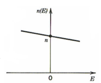
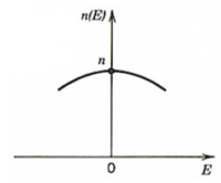
Electric impermeability of a material can be expressed as:
- <math>n \equiv \frac {\epsilon_0}{\epsilon} = \frac{1}{n^2}\,\!</math>
- <math>\eta (E) = \eta + rE +SE^2\,\!</math>
Where
- <math>\epsilon_0\,\!</math> is the dielectric constant of free space
- <math>\epsilon\,\!</math> is the dielectric constant
Pockels effect
In the Pockels effect an applied electric field changes the refractive index of certain materials.
- <math>\eta(E) = \eta - \frac {1} {2}rn^3 E\,\!</math>
Where:
r is Pockels coefficient or Linear Electro-optic Coefficient, r~ 10-12 – 1—10 m/V, typically.
This is a linear function with respect to the electric field, the higher the r the greater the change. It is cubic with respect to the refractive index so materials with high intrinsic refractive indexes will change more. Some examples include NH4H2PO4(ADP), KH2PO4(KDP), LiNbO3, LiTaO3, CdTe
The Kerr effect
- <math>\eta(E) = \eta – ½ Sn^3E^2\,\!</math>
Where
S is the Kerr coefficient
- S~ 10-18 – 10-14 mV in crystals
- S~ 10-22 – 10-19 mV in liquids
This is similar to the Pockels effect except that the refractive index varies parabolically or quadratically with the electric field.
This a process that occurs in second order nonlinear optical materials. It is a third order nonlinear optical process. Not all materials are second order nonlinear optical materials, only those that are centrosymmetric. However all materials have a χ(3) even if they are centrosymmetric.
It is possible to change the amplitude, phase or path of light at a given frequency by using a static DC electric field to polarize the material and modify the refractive indices. When light enters a material with a higher refractive index it is phase shifted and the waves become compressed. The direction is also changed. So by changing the refractive index it is possible to change the path of the light.
Consider the special case :<math>\omega_2 = 0\,\!</math> [equation (15)] in which a DC electric field is applied to the material.
The optical frequency polarization (Popt) arising from the second-order susceptibility is given by:
- <math>P_{opt} =\chi^{(2)}·E_1E_2(cos \omega_1 t)\,\!</math> (17)
where:
E1
E2 is the magnitude of the electric field caused by voltage applied to the nonlinear material (a voltage not optical frequency).
Recall that the refractive index is related to the linear susceptibility that is given by the second term of Equation (14):
- <math>\chi^{(1)}·E_1(cos \omega_1 t)\,\!</math> (18)
The total optical frequency polarization (Popt) is the χ(1) term plus the χ(2) term:
- <math>P_{opt} = \chi^{(1)}·E_1(cos_1t) +\chi^{(2)}·E_1E_2(cos \omega_1t)\,\!</math> (19)
Then factor out <math>E_1(cos \omega_1t)\,\!</math> :
- <math> P_{opt} = [\chi^{(1)} + \chi^{(2)}·E_2] E_1(cos \omega_1t)\,\!</math> (20)
χ(1) is linear susceptibility which relates to the dielectric constant, which in turn relates to the square of the refractive index. A change in the linear susceptiblity changes the index of refraction. The second term: χ(2) times the magnitude of the voltage (E2) means that the susceptibility of the material, the dielectric constant of the material, and the refractive index of the material can be altered by changing the applied voltage.
You can shine light on second order nonlinear optical materials and get out different frequencies, or shine one laser beam, apply an electric field and then modulate the refractive index. For example, light can travel freely between two fibers that are very close to each other with the same refractive index. But if the fibers have a different refractive index light will stay in one fiber or the other.
By changing the refractive index you can move light from one fiber to another; it provides a means of switching light in waveguides.
Summary
- The applied field in effect changes the linear susceptibility and thus the refractive index of the material.
- This is, known as the linear electro-optic (LEO) or Pockels effect, and is used to modulate light by changing the applied voltage.
- At the atomic level, the applied voltage is anisotropically distorting the electron density within the material. Thus, application of a voltage to the material causes the optical beam to "see" a different material with a different polarizability and a different anisotropy of the polarizability than in the absence of the voltage.
- Since the anisotropy is changed upon application of an electric field, a beam of light can have its polarization state (i.e., ellipticity) changed by an amount related to the strength and orientation of the applied voltage, and travel at a different speed and possibly in a different direction.
Index modulation
Quantitatively, the change in the refractive index as a function of the applied electric field is approximated by the general expression:
- <math>1/\underline{n}_{ij}2 = 1/n_{ij}2 + r_{ijk}E_k + s_{ijkl}E_kE_l + ... \,\!</math> (21)
where
- <math>\underline{n}_{ij}\,\!</math> are the induced refractive indices,
- <math>n_{ij}\,\!</math> is the refractive index in the absence of the electric field,
- <math>r_{ijk}\,\!</math> is the linear or Pockels coefficients, Δn for E = 106 V/m is 10-6 to 10-4 (crystals) and;
- <math>s_{ijkl}\,\!</math> are the quadratic or Kerr coefficients.
r coefficients
The optical indicatrix (that characterizes the anisotropy of the refractive index) therefore changes as the electric field within the sample changes. The map of index of refraction with respect to each polarization of light produces a surface that looks something like a football. The electric field allows you to change the shape of the football.
Electro-optic coefficients are frequently defined in terms of rijk. The "r" coefficients form a tensor (just as do the coefficient of α).
The subscripts ijk are the same as those used with β. The first subscript (i) refers to the resultant polarization of the material along a defined axis and the following subscripts j and k refer to the orientations of the applied fields, one is the optical frequency field and k is the voltage.
Applications of Electro-optic Devices
A network has a variety of devices that provide input from to a transmitter, connected by a electro-optic modulator (EOM) through a switching network, to a receiver with a photodetector, and then are connected to display devices. Nonlinear optical materials can be used for any of these applications. They can used to create terahertz radiation and to create specific wavelengths of light for spectroscopy.
| Return to Second-order Processes Menu | Next Topic |
