Optical Fibers
| Return to Optical Fibers, Waveguides, and Lasers Menu | Next Topic |
Optical Fiber
Visible light has a frequency of 1014 Hz . A light signal can be modulate at much higher frequencies than either radio or micowave. The movement from electrons to photonics is driven by the desire to create communication channels using high frequency carriers and which have extremely high information content . This requires that light be guided and controlled in precise ways, over long distances. Optical fibers can carry data at a rate of gigabytes per second, or the equivalent of several thousand phone conversations in parallel.
History
In 1870 Tyndall demonstrated that light could be guided within a water jet as a result of total internal reflection.
In 1954 it was proposed to create a cladded dielectric waveguide that has a core with a higher refractive index than the cladding.
In the mid 1960s research turned to building a communication system based on circular dielectric waveguides.
Circular Dielectric Waveguides
A circular dielectric waveguide or fiber optic has an internal core that has a lower index of refraction than the cladding.
At a certain diameter there is an angle such that there is total internal reflection. We can use mathematics to determine how to improve the material for less loss over longer distances.
The plane of incidence is a plane containing both the axis of the beam and the normal (perpendicular line) to the interface. For the flat drawing shown that would be the plane of the screen. A wave vector can be decomposed into a component that is perpendicular to the plane and a component that is parallel to the plane.
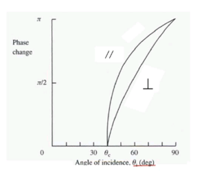
For an electric field vector that is perpendicular to the plane of incidence the phase is 2 ψ where:
- <math>tan \psi = \frac {[sin^2 \theta_i – (n_2/n_1)^ 2 ]^{1/2}} {cos \theta_i}\,\!</math>
For an electric field vector that is parallel to the plane of incidence the phase change is 2 δ where
- <math>tan \delta = (n_1/n_2)^2 tan \psi\,\!</math>
So as a function of the index of refraction there is change in phase of the reflected beam as it interacts with the material. This will be critical in determining how a beam propagates.
Here is an example using a glass air interface. The glass (n1) has an index of refraction of 1.5 and air (n2) is 1.0 and the critical angle (θ c) is 41.8 deg. The graph shows that phase change increases as the beam becomes more parallel with the interface.
All the energy in the beam is reflected when theta i > θ c
In the second medium the electric field amplitude decays exponentially with distance away from the boundary. The part of the field in the second medium is referred to as the evanescent field. The evanescent field can be measured using thin film techniques because the exponential decay means it does not penetrate far into the medium.
