Difference between revisions of "Lasers and Telecommunication- Outreach Kit"
Cmditradmin (talk | contribs) m (→User Guide) |
Cmditradmin (talk | contribs) m (→User Guide) |
||
| Line 49: | Line 49: | ||
6) '''Telecommunications depend on the ability to turn light on and off quickly (modulation).''' Show how the polarizing filter can pass or block light from the laser pointer. | 6) '''Telecommunications depend on the ability to turn light on and off quickly (modulation).''' Show how the polarizing filter can pass or block light from the laser pointer. | ||
<br clear='all'> | |||
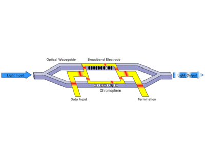
[[Image:MachZehnder.gif|thumb|400px|]] | [[Image:MachZehnder.gif|thumb|400px|]] | ||
7) '''Coherent light can be modulated by using interference of light waves.''' The Mach-Zehnder (MZ) interferometer is a device used to modulate light. In the MZ device a light beam is divided into two paths and one path goes through some electro-optic material. Changing the electric field on the EO material changes its index of refraction. When the two paths converge again destructive interference cancel the output light creating a signal. | 7) '''Coherent light can be modulated by using interference of light waves.''' The Mach-Zehnder (MZ) interferometer is a device used to modulate light. In the MZ device a light beam is divided into two paths and one path goes through some electro-optic material. Changing the electric field on the EO material changes its index of refraction. When the two paths converge again destructive interference cancel the output light creating a signal. | ||
Revision as of 15:55, 10 November 2009
| Previous Topic | K-12 Outreach Kits |
Overview
One of the major research thrusts of CMDITR is organic electronics that can be used in information technology and telecommunications. At the heart of this is the modulation of light using new organic electro-optical materials. Students need to understand how the system currently uses light and optics to carry information. Electro-optic materials can change their index of refraction in the presence of an electric field. This property combined with wave interference makes high speed switching possible. Finally, electro-optical and all optical switches can be miniaturized to the nano-scale to take advantage of other unique properties in device design.
Materials in the kit
- laser pointer
- plastic tub
- plastic tubing
- Optic fiber receiver and transmitter
- Michelson interferometer
User Guide
1) Information can be carried by modulating electrical signals either analog (continuously changing) or digital (timed pulses either on or off). Show or draw pictures of waveforms of analog and digital signals.
2) Information can be carried by light. Bounce a laser off of mirror attached to a balloon stretched on a can. Tap the rubber membrane or speak into it. Brainstorm the advantages of using light as carrier for information?
- CMDITR is working on ways to modulate light by controlling the optical properties of the materials it passes through. This may lead to improved efficiency of switching light in communication systems. It also may lead to all-optical switching (AOS) in which light from one channel controls light in another channel.
3) Optic fiber transmits light due to total internal reflection. Demonstrate light reflecting inside of plastic hose filled with water. Fill the plastic chamber with water and add a pinch of dry milk powder to reveal the light rays. Demonstrate the critical angle where there is total internal reflection. Place a wood plug in the hole in the plastic bottle and fill the bottle with water, place it on top of the plastic case. Position the laser in the support so that it points directly at the end of the plug. Place the larger plastic tub below the stream path. Turn on the laser and pull the plug. Use a white card to interrupt the stream and demonstrate that light is internally reflected in the stream.
4) Light is refracted and reflected when it encounters a material with a different index of refraction. Place a straw in the plastic tub with water (add a little milk to visualize laser) and observe that it appears to bend when placed at an angle. Repeat the demonstration this time with a laser pointed down from above. Index of refraction is the ratio of the speed of light in a vacuum over to that in the material. Air and water have very different indexes of refraction.
Solids and liquids can have different indexes of refraction. Carefully pour a layer of 80% sugar solution or corn syrup into the bottom of the plastic container. Tell students that sugar water has index of refraction of 1.49 and pure water is 1.33. Repeat the refraction demo. The light should bend a second time when it reaches the sugar water layer. Another variation is to carefully mix a series of sugar solutions and layer them so the solution is progressively more dense. This will result in a smoothly bending straw or light beam.
- This property is used in optic fiber in which the core and cladding have different IOR. Some fibers use the graded index fiber with special glass or polymers with progressively higher IOR. This decreases the dispersion of light that is caused by light at different angles passing through the fiber at different speeds (modal dispersion).
5) Fiber optics are used to transmit signals over long distances for phone and computer networks, or short distances between computer servers where high speed connections are needed. This usually involves transferring from electrical to optical and back to electrical signals. The optical fiber communications demonstration kit includes a transmitter and a receiver. Apply the 5V power supply to the demonstration device. This demo shows one way communication. (for two way communication the system would have a receiver and transmitter at both ends). The transmitter has a simple oscillator that controls an LED at the point where the optical fiber enters the device. Light passes along the fiber to the receiver where a photo detector senses the light and the circuitry coverts the light back into electricity at the Data output lines. Connect EN and EXT on the transmitter to the +5V positive terminal. An LED will flash on the Data lines on the receiver, proving that the signal has made it all the way back to electricity again. Disconnect the optical fiber from the receiver end and show that that the fiber end is flashing, the LED on the data will stop flashing when it stops getting its optical signal. As you bring the fiber back into the receiver the LED will begin flashing again.
The circuit is controlled with the following logic on the transmitter side. 0 means the line is connected to the ground, 1 means it is connected to the +5V line.
Mode EN EXT LED State
1 0 1 ON
2 0 0 OFF
3 1 1 OSCILLATING
4 1 0 OFF
- CMDITR researchers are concerned with various aspects of the optical network. An electro-optical switch can built using polymers. A key problem is switching speed. New organic molecules may be able to operate at higher speeds than current materials.
6) Telecommunications depend on the ability to turn light on and off quickly (modulation). Show how the polarizing filter can pass or block light from the laser pointer.
7) Coherent light can be modulated by using interference of light waves. The Mach-Zehnder (MZ) interferometer is a device used to modulate light. In the MZ device a light beam is divided into two paths and one path goes through some electro-optic material. Changing the electric field on the EO material changes its index of refraction. When the two paths converge again destructive interference cancel the output light creating a signal.
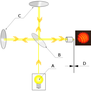
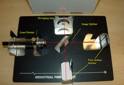
The Michelson Interferometer demonstrates this kind of interference with a more complicated path. One path of the split beam goes through the beam splitter, reflects off a mirror, then reflects off the back side of the image splitter and finally reflect off a second mirror before exiting the beam splitter along the original path. The two beams then pass through a diverging lens to spread the beam out into a wider area to reveal a series of bands or circles where there has been interference. This device is extremely sensitive to distance (for visible light it is 1/100th the thickness of human hair. This makes it sensitive to minute vibrations and minute changes in the index of refraction of material placed in the path.
Follow the manufacturer’s instructions for arranging the pieces for the interferometer demo. Once you get a somewhat stable interference pattern then experiment with placing glass in the path. By turning the glass slightly you will alter its effective index of refraction and cause a shift in the interference pattern. Similarly, when an electro-optical material is placed in the beam path it will alter the interference pattern. A variation on this setup can be used to measure the electro-optic coefficient of materials.
- CMDITR research is building materials that can be used in telecom and all optical switching.
8) New materials can be fashioned into extremely small nano-scale devices integrated right on to the chip. Show photos, discuss micro-electronic trends, fabrication and scale.


