Difference between revisions of "Organic Heterojunctions"
Cmditradmin (talk | contribs) m (→Voltammograms) |
|||
| (19 intermediate revisions by 2 users not shown) | |||
| Line 1: | Line 1: | ||
[[Main_Page# | <table id="toc" style="width: 100%"> | ||
[[Fluorescent/Phosphorescent Dopants|Next Topic]] | <tr> | ||
==Organic | <td style="text-align: left; width: 33%">[[OLED Charge Mobilities|Previous Topic]]</td> | ||
<td style="text-align: center; width: 33%">[[Main_Page#Organic_Light_Emitting_Diodes|Return to OLED Menu]]</td> | |||
<td style="text-align: right; width: 33%">[[Fluorescent/Phosphorescent Dopants|Next Topic]]</td> | |||
</tr> | |||
</table> | |||
==Organic Heterojunctions== | |||
The mobility for electrons passing into the HTL is much lower than the mobility of holes passing into the ETL. In recent years there has success in balancing these mobilities but even in polymer light emitting diodes it is still a problem. | The mobility for electrons passing into the HTL is much lower than the mobility of holes passing into the ETL. In recent years there has success in balancing these mobilities but even in polymer light emitting diodes it is still a problem. | ||
To make a practical OLED there are these considerations: | To make a practical OLED there are these considerations: | ||
| Line 7: | Line 16: | ||
*Its desirable to match the charge mobilities in HTL and ETL layers. Some researchers have tried to slow down the hole injection so as to keep the arrival of the holes matched with the arrival of the electrons. This approach can be used up to a point. | *Its desirable to match the charge mobilities in HTL and ETL layers. Some researchers have tried to slow down the hole injection so as to keep the arrival of the holes matched with the arrival of the electrons. This approach can be used up to a point. | ||
*You want localize the emission of zone to the center of the device. It possible to inject a hole from the HTL into the ETL. However, it is better to have the charges collect at the interface and undergo a cross reaction to generate the emissive state. | *You want localize the emission of zone to the center of the device. It possible to inject a hole from the HTL into the ETL. However, it is better to have the charges collect at the interface and undergo a cross reaction to generate the emissive state. | ||
<embed_document align=right width="55%" height="400">http://depts.washington.edu/cmditr/mediawiki/images/b/bb/Oled7banddistribution.pdf</embed_document> | |||
This simplified diagram shows the change in band position-- potential energy as a function of distance across the device when the devices is under a positive bias. This assumes a common vacuum level which is not quite correct. Electrons and holes build up at the heterojunction. | This simplified diagram shows the change in band position-- potential energy as a function of distance across the device when the devices is under a positive bias. This assumes a common vacuum level which is not quite correct. Electrons and holes build up at the heterojunction. | ||
| Line 16: | Line 27: | ||
These are the typical components of a heterojunction OLED that are used in many labs. TPD is a well known Bis triarylamine which is easy to oxidize and forms a very stable cation radical because of the resonance stabilization between the two nitrogen centers. Its energy level is shown missing an electron. These can have lifetimes in dry solvents of up seconds to minutes so they extremely stable. They are very strongly colored. It is used in the hole transport layer. | These are the typical components of a heterojunction OLED that are used in many labs. TPD is a well known Bis triarylamine which is easy to oxidize and forms a very stable cation radical because of the resonance stabilization between the two nitrogen centers. Its energy level is shown missing an electron. These can have lifetimes in dry solvents of up seconds to minutes so they extremely stable. They are very strongly colored. It is used in the hole transport layer. | ||
Aluminum tris quinolate is a typical emissive material and the electron transport material with a very high quantum yield for emission. It is reducible. The lifetime in solution of the one electron reduced state is short. It is unstable and quite reactive. | Aluminum tris quinolate (Alq<sub>3</sub>)is a typical emissive material and the electron transport material with a very high quantum yield for emission. It is reducible. The lifetime in solution of the one electron reduced state is short. It is unstable and quite reactive. | ||
When these two species encounter each other across the interface of an OLED an electron transfer event takes place. The resultant excess free energy is deposited in the lower bandgap of the two materials which in this case is the ETL material. This is what creates the green emission in the LED. | When these two species encounter each other across the interface of an OLED an electron transfer event takes place. The resultant excess free energy is deposited in the lower bandgap of the two materials which in this case is the ETL material. This is what creates the green emission in the LED. | ||
<br clear="all"> | <br clear="all"> | ||
These are | === Voltammograms === | ||
[[Image:OLED7_voltagrams.JPG|thumb|400px|Voltammograms for OLED components<ref>J. Phys. Chem. B, 2003, 107 (5), pp 1142–1150 {{Doi|10.1021/jp021368g}}</ref>]] | |||
These are cyclic voltammograms for various components that might be of use in building OLEDs. | |||
Following TPD, as we sweep towards the positive is the first one electron oxidation and then a second, and then the reduction of the di-cation radical and then the reduction of the cation radical back to the neutral state. In an OLED we only worry about the first of the two one electron transfer processes. | Following TPD, as we sweep towards the positive is the first one electron oxidation and then a second, and then the reduction of the di-cation radical and then the reduction of the cation radical back to the neutral state. In an OLED we only worry about the first of the two one electron transfer processes. | ||
| Line 28: | Line 43: | ||
If you go far enough positive Alq<sub>3</sub> it will be undergo oxidation but it is chemically irreversible. This is why you want to avoid hole injection to this layer. On the other had it very hard to reduce TPD, therefore we are only concerned with one electron oxidation. | If you go far enough positive Alq<sub>3</sub> it will be undergo oxidation but it is chemically irreversible. This is why you want to avoid hole injection to this layer. On the other had it very hard to reduce TPD, therefore we are only concerned with one electron oxidation. | ||
So in an experimental cell with both components in the cell at the same time we rapidly pulse the electrode forming the radical anion state of | So in an experimental cell with both components in the cell at the same time we rapidly pulse the electrode forming the radical anion state of Alq<sub>3</sub>, reverse the charge and form the radical cation of the TPD. The two molecule diffuse together near the electron solution interface where they undergo electron transfer reactions they emit light which can leaves the cell through the window. | ||
We developed Aluminum tris suphonamide quinolate (Al(qs)<sub>3</sub>) at U of A. By adding the sulphonamide substituent to the 8 hydroxy quinolin ring we made the molecule much easier to reduce. The diagram show three one electron reductions however only the first is relevant for OLED production. | We developed Aluminum tris suphonamide quinolate (Al(qs)<sub>3</sub>) at U of A. By adding the sulphonamide substituent to the 8 hydroxy quinolin ring we made the molecule much easier to reduce. The diagram show three one electron reductions however only the first is relevant for OLED production. | ||
| Line 36: | Line 51: | ||
DiQA , a quinacridone derivative is related to one of the first dopants used by Kodak to create the green OLED, has a very stable one electron reduction product and a very stable oxidation product as shown in the voltamograms. We are going to use this molecule to OLEDs and let it do both energy and charge capture to create a green emissive state. | DiQA , a quinacridone derivative is related to one of the first dopants used by Kodak to create the green OLED, has a very stable one electron reduction product and a very stable oxidation product as shown in the voltamograms. We are going to use this molecule to OLEDs and let it do both energy and charge capture to create a green emissive state. | ||
<br clear="all"> | |||
[[Image:Oled7-spins.JPG|thumb|400px|]] | |||
There is adequate excess free energy in the cross reaction between TPD<sup>+</sup> and Alq<sub>3</sub><sup>-</sup> to create an emissive state Alq<sub>3</sub>* which gives the green light. The number of emissive states generated per unit time is related to the rate coefficient for electron transfer which is turn related to the excess free energy in the cross reaction and the reorganization energy involved in undergoing that electron transfer. Marcus theory does apply. | There is adequate excess free energy in the cross reaction between TPD<sup>+</sup> and Alq<sub>3</sub><sup>-</sup> to create an emissive state Alq<sub>3</sub>* which gives the green light. The number of emissive states generated per unit time is related to the rate coefficient for electron transfer which is turn related to the excess free energy in the cross reaction and the reorganization energy involved in undergoing that electron transfer. Marcus theory does apply. | ||
There is the problem of spins statistics. We are going generation both the 24% singlet states and 75% triplet states. This will have an impact on the optimization of OLEDs. | There is the problem of spins statistics. We are going generation both the 24% singlet states and 75% triplet states. This will have an impact on the optimization of OLEDs. | ||
see Partridge 1983 <ref>Electroluminescence from PVK R.H. Partridge Polymer 24, 733 (1983)</ref> | |||
and Burroughes 1990 <ref>Light emitting conjugated polymers J. H. Burroughes, R.H. Friend et al Nature 347 539 (1990)</ref> | |||
== References == | |||
<references/> | |||
[[category:organic LED]] | |||
[[category:electronic band structure]] | |||
<table id="toc" style="width: 100%"> | |||
<tr> | |||
<td style="text-align: left; width: 33%">[[OLED Charge Mobilities|Previous Topic]]</td> | |||
<td style="text-align: center; width: 33%">[[Main_Page#Organic_Light_Emitting_Diodes|Return to OLED Menu]]</td> | |||
<td style="text-align: right; width: 33%">[[Fluorescent/Phosphorescent Dopants|Next Topic]]</td> | |||
</tr> | |||
</table> | |||
Latest revision as of 14:05, 8 November 2010
| Previous Topic | Return to OLED Menu | Next Topic |
Organic Heterojunctions
The mobility for electrons passing into the HTL is much lower than the mobility of holes passing into the ETL. In recent years there has success in balancing these mobilities but even in polymer light emitting diodes it is still a problem. To make a practical OLED there are these considerations:
- First minimize the injection barriers for both hole injection and electron injection. This decreases the drive voltage required to create light from the device.
- Its desirable to match the charge mobilities in HTL and ETL layers. Some researchers have tried to slow down the hole injection so as to keep the arrival of the holes matched with the arrival of the electrons. This approach can be used up to a point.
- You want localize the emission of zone to the center of the device. It possible to inject a hole from the HTL into the ETL. However, it is better to have the charges collect at the interface and undergo a cross reaction to generate the emissive state.
<embed_document align=right width="55%" height="400">http://depts.washington.edu/cmditr/mediawiki/images/b/bb/Oled7banddistribution.pdf</embed_document>
This simplified diagram shows the change in band position-- potential energy as a function of distance across the device when the devices is under a positive bias. This assumes a common vacuum level which is not quite correct. Electrons and holes build up at the heterojunction.
Holes can cross the barrier or holes can encounter an electron at the interface. They are energetically separated from each other but spatially seeing each other across the interface. The recombination process creates enough excess free energy to create an emissive state of the ETL molecular system and light is emitted towards the HTL layer.
Typical components of a single heterojunction OLED
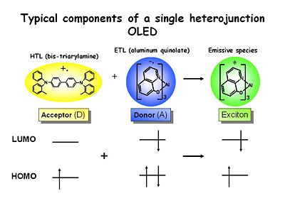
These are the typical components of a heterojunction OLED that are used in many labs. TPD is a well known Bis triarylamine which is easy to oxidize and forms a very stable cation radical because of the resonance stabilization between the two nitrogen centers. Its energy level is shown missing an electron. These can have lifetimes in dry solvents of up seconds to minutes so they extremely stable. They are very strongly colored. It is used in the hole transport layer.
Aluminum tris quinolate (Alq3)is a typical emissive material and the electron transport material with a very high quantum yield for emission. It is reducible. The lifetime in solution of the one electron reduced state is short. It is unstable and quite reactive.
When these two species encounter each other across the interface of an OLED an electron transfer event takes place. The resultant excess free energy is deposited in the lower bandgap of the two materials which in this case is the ETL material. This is what creates the green emission in the LED.
Voltammograms

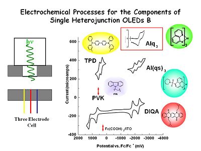
These are cyclic voltammograms for various components that might be of use in building OLEDs. Following TPD, as we sweep towards the positive is the first one electron oxidation and then a second, and then the reduction of the di-cation radical and then the reduction of the cation radical back to the neutral state. In an OLED we only worry about the first of the two one electron transfer processes.
For aluminum quinolate if we scan at very high sweep rates at a microelectrode we see a one electron reduction process and then the oxidation of the anion radical product. This does not remain stable at low sweep rates, it has a half life on the order of microseconds compared with second for TPD. Even with very clean solvents once you make the radical anion it will go out and find something else to reduce such as traces of oxygen or water. In the condense phase environment we can anticipate it will be much more stable.
If you go far enough positive Alq3 it will be undergo oxidation but it is chemically irreversible. This is why you want to avoid hole injection to this layer. On the other had it very hard to reduce TPD, therefore we are only concerned with one electron oxidation.
So in an experimental cell with both components in the cell at the same time we rapidly pulse the electrode forming the radical anion state of Alq3, reverse the charge and form the radical cation of the TPD. The two molecule diffuse together near the electron solution interface where they undergo electron transfer reactions they emit light which can leaves the cell through the window.
We developed Aluminum tris suphonamide quinolate (Al(qs)3) at U of A. By adding the sulphonamide substituent to the 8 hydroxy quinolin ring we made the molecule much easier to reduce. The diagram show three one electron reductions however only the first is relevant for OLED production.
Polyvinyl Carbazole (PVK) is harder to oxidize than TPD.
DiQA , a quinacridone derivative is related to one of the first dopants used by Kodak to create the green OLED, has a very stable one electron reduction product and a very stable oxidation product as shown in the voltamograms. We are going to use this molecule to OLEDs and let it do both energy and charge capture to create a green emissive state.
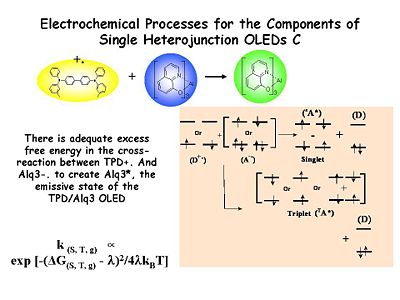
There is adequate excess free energy in the cross reaction between TPD+ and Alq3- to create an emissive state Alq3* which gives the green light. The number of emissive states generated per unit time is related to the rate coefficient for electron transfer which is turn related to the excess free energy in the cross reaction and the reorganization energy involved in undergoing that electron transfer. Marcus theory does apply.
There is the problem of spins statistics. We are going generation both the 24% singlet states and 75% triplet states. This will have an impact on the optimization of OLEDs.
see Partridge 1983 [2]
and Burroughes 1990 [3]
References
- ↑ J. Phys. Chem. B, 2003, 107 (5), pp 1142–1150 doi:10.1021/jp021368g
- ↑ Electroluminescence from PVK R.H. Partridge Polymer 24, 733 (1983)
- ↑ Light emitting conjugated polymers J. H. Burroughes, R.H. Friend et al Nature 347 539 (1990)
| Previous Topic | Return to OLED Menu | Next Topic |

