Difference between revisions of "Metal Complex Dopants"
Cmditradmin (talk | contribs) |
Cmditradmin (talk | contribs) |
||
| (6 intermediate revisions by 4 users not shown) | |||
| Line 3: | Line 3: | ||
<td style="text-align: left; width: 33%">[[Fluorescent/Phosphorescent Dopants|Previous Topic]]</td> | <td style="text-align: left; width: 33%">[[Fluorescent/Phosphorescent Dopants|Previous Topic]]</td> | ||
<td style="text-align: center; width: 33%">[[Main_Page#Organic_Light_Emitting_Diodes|Return to OLED Menu]]</td> | <td style="text-align: center; width: 33%">[[Main_Page#Organic_Light_Emitting_Diodes|Return to OLED Menu]]</td> | ||
<td style="text-align: right; width: 33%; color:#cccccc;">Next Topic</td> | |||
</tr> | </tr> | ||
</table> | </table> | ||
==Decreasing Triplet Lifetime== | |||
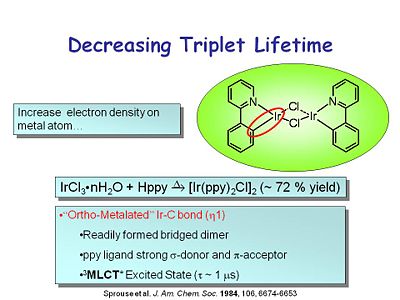
[[Image:oled10_tripletlife.JPG|thumb|400px|Using an ortho-metalated Ir-C bond to decrease the triplet lifetime.]] | |||
One of the key advances to the modern OLED was rediscovering heavy metal complexes that had very high phosphorescent quantum yields and short lifetimes. This class of compound has an iridium molecule at the center with both an iridium-nitrogen and an iridium-carbon bond, which has the characteristics of an ortho-metallated iridium-carbon bond. It readily forms a bridged dimer. The ppy ligand is a strong σ donor and π acceptor. The metal to ligand charge transfer excited state is a triplet with a lifetime of about 1 microsecond. | |||
This led to other ortho-metallated compounds such as the iridium tris ppy sytem, discovered in the 1980s. It has 3 complexing groups around the iridium center. The emission spectrum shows a large stokes shift from its absorption band and narrow emission in the green. | |||
==Ortho-Metallated Iridium Complexes== | |||
These represent a new class of phosphor. They are related to the tris bby complexes that are known for a number of metals, which have interactions with two nitrogens and the two bipyramidines. The metal-carbon bond has impact on the redox properties. The Ir(ppy)<sub>3</sub> form is much easier to oxidize than the Ru(bby)<sub>3</sub> system. | |||
Other phosphorescent dopants include iridium compounds with both | The PtOEP was one of the first triplet scavengers used in OLEDs. This can be compared with the fac-IR(ppy)<sub>3</sub>. PtOEP has an emission wavelength farther into the red. Both have a high quantum efficiency for phosphorescence, but PtOEP has a much longer lifetime. The external quantum yields are 1-2% for PtOEP while fac-IR(ppy)<sub>3</sub> has an efficiency of 8%. This was exciting. | ||
The most efficient device known at this time has an external efficiency of 13% at 1000 candelas (which is quite bright). It is a green emitter. These impressive numbers are the relevant quantum efficiency versus current density for the compound above compared to PtOEP. The quantum efficiency was constant from 1 mA to 100 mA, which allows the device to run at variable intensities. Eventually there is a drop off at high current densities, but you are most displays are never driven that high. | |||
Other phosphorescent dopants include iridium compounds with both iridium–nitrogen and iridium-carbon bonds. As you change the constituents of the other complex agents, the light emission changes from red to green to blue wavelengths. The narrower line widths indicate purer colors. | |||
See Sprouse 1984 <ref>Sprouse et al. J. Am. Chem. Soc. 1984, 106, 6674-6653</ref> | |||
==Future Directions for OLEDs: Color Purity== | ==Future Directions for OLEDs: Color Purity== | ||
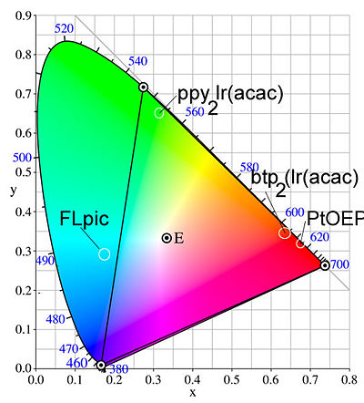
[[Image:Ciecolorpurity.jpg|thumb|400px|Broad emission limits color purity. Graph shows the colors possible by mixing CIE x and y coordinates]] | [[Image:Ciecolorpurity.jpg|thumb|400px|Broad emission limits color purity. Graph shows the colors possible by mixing CIE x and y coordinates]] | ||
The idea of color purity is important. The CIE color chart shows the coordinates that you must hit if you want to get pure red, pure blue or pure green. | The idea of color purity is important. The CIE color chart shows the coordinates that you must hit if you want to get pure red, pure blue or pure green. To combine them, the coordinate must be in the central region. This is based on the eye’s sensitivity to these colors, and is important to the display business. PtOEP is a good red. The green could be better and the blue is not a pure blue. Subsequent to this, other compounds have been developed that hit the CIE color coordinates nicely. | ||
Lanthanides give extremely narrow line shapes for both emission and absorption. Unfortunately these are not very efficient compared to the heavy metal complexes. The color purity is attributed to their f-f transitions. | Lanthanides give extremely narrow line shapes for both emission and absorption. Unfortunately these are not very efficient compared to the heavy metal complexes. The color purity is attributed to their f-f transitions. | ||
The efficiency of blue emitters lags behind red and green due to the lack of suitable hosts. Blue emission is harder to get because it requires radical anions and radical cations which are the most positive and the most negative in terms of electrochemical potentials | The efficiency of blue emitters lags behind red and green due to the lack of suitable hosts. Blue emission is harder to get because it requires radical anions and radical cations which are the most positive and the most negative in terms of electrochemical potentials. They also have the highest excess free energy in the recombination reaction leading to the excited state. These generate the least stable radical species, the ones most likely to react with oxygen and water. There are fewer compounds that emit in the blue spectrum. Silicon-based compounds with a photoluminescent emission spectrum well into the ultraviolet could be used as host materials for phosphorescent blue dopants. These are still being developed. | ||
We can build very thin light sources. There are | We can build very thin light sources. There are multiple factors that limit efficiency, including the interface between the transparent conductor and the hole transport layer, and the cathode interface with the electron transport layer. As efficiency improves, multilayer devices are being developed with 4 or 5 heterojunctions- each with their own dopants, to produce full red, green and blue emission. | ||
Common molecules and their wavelengths: | |||
*Aluminum quinolate | *Aluminum quinolate (green) | ||
*Eu(TTA)<sub>3</sub> | *Eu(TTA)<sub>3</sub> (red) | ||
*Platinum ocoethyl porphyrin PtOEH | *Platinum ocoethyl porphyrin PtOEH (red phosphorescent dopant) | ||
*DCM2 was a laser dye used by the Kodak group to shift the emission into the red region | *DCM2 was a laser dye used by the Kodak group to shift the emission into the red region | ||
*Coumarin -6 | *Coumarin -6 (green dopant) | ||
*Alq<sub>2</sub> OPH | *Alq<sub>2</sub> OPH (blue) | ||
White light for room lighting is an important application. | White light for room lighting is also an important application. | ||
At an OLED fabrication facility, a glass substrate is loaded at the back, and the conductive layer is added. Each vacuum stage allows you to put down a different layer. Typically, the sublimation sources are loaded with 5-50 grams or material, and it can be a challenge for organic chemists to produce such high volumes. | |||
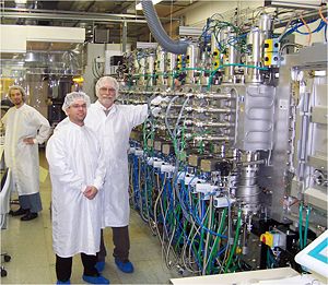
[[Image:OLED_Fabrication_Line.jpg|thumb|300px|Neal Armstrong at Fraunhofer Institute Fabrication Line]] | [[Image:OLED_Fabrication_Line.jpg|thumb|300px|Neal Armstrong at Fraunhofer Institute Fabrication Line]] | ||
[[category:organic LED]] | [[category:organic LED]] | ||
<br clear='all'> | |||
== References == | |||
<references/> | |||
<table id="toc" style="width: 100%"> | <table id="toc" style="width: 100%"> | ||
Latest revision as of 11:14, 1 December 2009
| Previous Topic | Return to OLED Menu | Next Topic |
Decreasing Triplet Lifetime
One of the key advances to the modern OLED was rediscovering heavy metal complexes that had very high phosphorescent quantum yields and short lifetimes. This class of compound has an iridium molecule at the center with both an iridium-nitrogen and an iridium-carbon bond, which has the characteristics of an ortho-metallated iridium-carbon bond. It readily forms a bridged dimer. The ppy ligand is a strong σ donor and π acceptor. The metal to ligand charge transfer excited state is a triplet with a lifetime of about 1 microsecond.
This led to other ortho-metallated compounds such as the iridium tris ppy sytem, discovered in the 1980s. It has 3 complexing groups around the iridium center. The emission spectrum shows a large stokes shift from its absorption band and narrow emission in the green.
Ortho-Metallated Iridium Complexes
These represent a new class of phosphor. They are related to the tris bby complexes that are known for a number of metals, which have interactions with two nitrogens and the two bipyramidines. The metal-carbon bond has impact on the redox properties. The Ir(ppy)3 form is much easier to oxidize than the Ru(bby)3 system.
The PtOEP was one of the first triplet scavengers used in OLEDs. This can be compared with the fac-IR(ppy)3. PtOEP has an emission wavelength farther into the red. Both have a high quantum efficiency for phosphorescence, but PtOEP has a much longer lifetime. The external quantum yields are 1-2% for PtOEP while fac-IR(ppy)3 has an efficiency of 8%. This was exciting.
The most efficient device known at this time has an external efficiency of 13% at 1000 candelas (which is quite bright). It is a green emitter. These impressive numbers are the relevant quantum efficiency versus current density for the compound above compared to PtOEP. The quantum efficiency was constant from 1 mA to 100 mA, which allows the device to run at variable intensities. Eventually there is a drop off at high current densities, but you are most displays are never driven that high.
Other phosphorescent dopants include iridium compounds with both iridium–nitrogen and iridium-carbon bonds. As you change the constituents of the other complex agents, the light emission changes from red to green to blue wavelengths. The narrower line widths indicate purer colors.
See Sprouse 1984 [1]
Future Directions for OLEDs: Color Purity
The idea of color purity is important. The CIE color chart shows the coordinates that you must hit if you want to get pure red, pure blue or pure green. To combine them, the coordinate must be in the central region. This is based on the eye’s sensitivity to these colors, and is important to the display business. PtOEP is a good red. The green could be better and the blue is not a pure blue. Subsequent to this, other compounds have been developed that hit the CIE color coordinates nicely.
Lanthanides give extremely narrow line shapes for both emission and absorption. Unfortunately these are not very efficient compared to the heavy metal complexes. The color purity is attributed to their f-f transitions.
The efficiency of blue emitters lags behind red and green due to the lack of suitable hosts. Blue emission is harder to get because it requires radical anions and radical cations which are the most positive and the most negative in terms of electrochemical potentials. They also have the highest excess free energy in the recombination reaction leading to the excited state. These generate the least stable radical species, the ones most likely to react with oxygen and water. There are fewer compounds that emit in the blue spectrum. Silicon-based compounds with a photoluminescent emission spectrum well into the ultraviolet could be used as host materials for phosphorescent blue dopants. These are still being developed.
We can build very thin light sources. There are multiple factors that limit efficiency, including the interface between the transparent conductor and the hole transport layer, and the cathode interface with the electron transport layer. As efficiency improves, multilayer devices are being developed with 4 or 5 heterojunctions- each with their own dopants, to produce full red, green and blue emission.
Common molecules and their wavelengths:
- Aluminum quinolate (green)
- Eu(TTA)3 (red)
- Platinum ocoethyl porphyrin PtOEH (red phosphorescent dopant)
- DCM2 was a laser dye used by the Kodak group to shift the emission into the red region
- Coumarin -6 (green dopant)
- Alq2 OPH (blue)
White light for room lighting is also an important application.
At an OLED fabrication facility, a glass substrate is loaded at the back, and the conductive layer is added. Each vacuum stage allows you to put down a different layer. Typically, the sublimation sources are loaded with 5-50 grams or material, and it can be a challenge for organic chemists to produce such high volumes.
References
- ↑ Sprouse et al. J. Am. Chem. Soc. 1984, 106, 6674-6653
| Previous Topic | Return to OLED Menu |


