Difference between revisions of "Organic Field Effect Transistors"
Cmditradmin (talk | contribs) m |
|||
| (7 intermediate revisions by 2 users not shown) | |||
| Line 34: | Line 34: | ||
\sqrt{\mu} \propto \frac {\sqrt {I_{DS}}}{V_{GS}}\,\!</math> | \sqrt{\mu} \propto \frac {\sqrt {I_{DS}}}{V_{GS}}\,\!</math> | ||
=== Simulation === | |||
=== <div id="Flash">OFET Simulation</div> === | |||
Use this simulation to explore N-type, P-type and ambipolar semiconductor polymers in an organic field effect transistor. | Use this simulation to explore N-type, P-type and ambipolar semiconductor polymers in an organic field effect transistor. | ||
You can control the gate voltage and the voltage across the circuit. | You can control the gate voltage and the voltage across the circuit. | ||
<swf width="600" height="500">images/6/64/Ofet.swf</swf> | |||
=== External Links === | |||
[[wikipedia:Field_effect_transistor]] | |||
[http://micro.magnet.fsu.edu/electromag/java/transistor/ Build an FET] | |||
[[category:organic field effect transistor]] | |||
Latest revision as of 12:59, 2 November 2011
| Previous Topic | Return to Organic Electronics Menu | Next Topic |
Organic Field Effect Transistors
A field effect transistor (FET) uses an electric field to change the conductivity of an semiconductor material. An organic field effect transistor (OFET) uses an electrically active organic compound as the switching component.
There are three major processes involved with organic field-effect transistors; charge injection, charge transport, and charge collection.
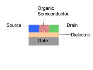
The first one is the injection of charges into the semi-conductor. In the case of light-emitting diode and photovoltaic cell there are only two electrodes. However, in a field-effect transistor, the charge injection is modulated through a third electrode called a gate. Now all is needed are the electrons and the holes. Let’s suppose you inject electrons. Those electrons must migrate and be collected. The first electrode will be referred to as a gate. Next there is a thin insulator called a dielectric. You have two other electrodes referred to as the source and the drain. The organic semi-conductor sits between these. This is one of the configurations possible.
When there is a voltage difference between the source and drain, the amount of charges that will be injected into the semi-conductor will be modulated by the voltage at the gate. The gate will modulate the injection and produce a switching effect. For a given voltage between the source and drain, the voltage of the gate can either be decreased such that there is a small injection or current or it can be increased to have a very large injection of charges into the semi-conductor and a large current. These are the components that make a transistor also called a three terminal device because there are 3 electrodes.
Following injection of charges into the organic semi-conductor, those charges will travel and be collected at the other electrodes.
- <math>I_{DS} = \frac {WC_i} {2L} \mu ( V_{GS} - V_T) ^2\,\!</math>
where
- <math>I_{DS}\,\!</math> is the current between the drain and source
- <math>I_{GS}\,\!</math> is the Voltage between gate and source
- <math>\mu\,\!</math> is the mobility
furthermore
- <math>
\sqrt{\mu} \propto \frac {\sqrt {I_{DS}}}{V_{GS}}\,\!</math>
OFET Simulation
Use this simulation to explore N-type, P-type and ambipolar semiconductor polymers in an organic field effect transistor.
You can control the gate voltage and the voltage across the circuit.
<swf width="600" height="500">images/6/64/Ofet.swf</swf>
