Difference between revisions of "External quantum efficiency"
Cmditradmin (talk | contribs) m (→Operation) |
Cmditradmin (talk | contribs) m (→Operation) |
||
| Line 12: | Line 12: | ||
=== Operation === | === Operation === | ||
{{#ev:youtube| | EQE Part1 | ||
{{#ev:youtube| | {{#ev:youtube|zKagkC2n-rU}} | ||
EQE Part2 | |||
{{#ev:youtube|yxggrSciBnM}} | |||
Ideally the calibrated photodiode should be the same size as the illuminated area of the test sample. Otherwise even though the photodiode is masked to the same area as the test pixel there is the possibility of measuring dark currents from the remaining area of the photodiode. | Ideally the calibrated photodiode should be the same size as the illuminated area of the test sample. Otherwise even though the photodiode is masked to the same area as the test pixel there is the possibility of measuring dark currents from the remaining area of the photodiode. | ||
Revision as of 13:09, 19 January 2010
| Return to Research Tool Menu |
Overview
External Quantum Efficiency (EQE) for a photovoltaic device is the number of extracted free charge carriers per incident photon. This ratio is obtained by measuring the photocurrent spectrum of the photovoltaic device under test and comparing it to the photocurrent spectrum of a calibrated photodetector, thereby removing the spectral characteristics of the test system. Relative and arbitrary unit EQE measurements can be obtained quite easily when care is taken to ensure similar test conditions for each device under test. Quantitatively accurate measurements require the user to pay attention to details such as illumination intensity and flux distribution of the light source[ref], optical reflectance and interference in device and test chamber[refs], device temperature[ref], and also the definition of the effective active area[ref]. With all of these considerations in addition to the variability of device fabrication protocol in different laboratories, the standardized power conversion efficiency measurement may make the best universal benchmark for device performance. However, the EQE measurement can be broken up into different spectral components and allows for the comparison and analysis of device physics.
see Wikipedia External Quantum Efficiency
Operation
EQE Part1
EQE Part2
Ideally the calibrated photodiode should be the same size as the illuminated area of the test sample. Otherwise even though the photodiode is masked to the same area as the test pixel there is the possibility of measuring dark currents from the remaining area of the photodiode.
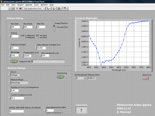
The monochromator is controlled by a customized Lab View application and the software automatically records photocurrent from the device at a specified series of wavelengths.
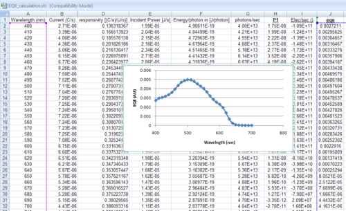
This produces an series of wavelength / current data pairs which can be brought into Excel to calculated EQE graph the results.
The spreadsheet columns are as follows.
- A- Wavelength in nm
- B- Photocurrent spectra from NIST calibrated photodiode- C/s
- D- Responsivity from lab generated calibration data for photodiode [(C/s) / (J/s)]
- E- Incident power in J/s calculated by dividing photocurrent by responsivitiy (B2/D2)
- F- Energy per photon in J/photon- (E=hc/λ) calculated as 6.626068 x 10-34 * 299792458 * 1000000000/A2
- G- Photons per second = Incident power divided by Energy per photon (E2/F2)
- H- Measured device photocurrent in C/s
- I- Electrons per second = -6241509629152650000 * photocurrent (H2)
- J- EQE = electrons per second/ incident photons per second (E2/F2)
Significance
- ↑ article

