Difference between revisions of "Propagation, Reflection and Refraction"
Cmditradmin (talk | contribs) |
|||
| Line 24: | Line 24: | ||
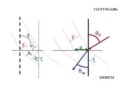
Air has a refractive index that is close to 1.The illustration shows light approaching a surface with a wavelength <math>\lambda_0\,\!</math> measured as the distance between wave crests. When light passes from air into another medium there is distance between wave crests as they enter the medium identified as d. At the surface the distance d must be the same for the incident beam and the diffracted beam. When the light enters the new materials light is slowed down while the frequency stays the same, this means that the diffracted beam must have a smaller wavelength. | Air has a refractive index that is close to 1.The illustration shows light approaching a surface with a wavelength <math>\lambda_0\,\!</math> measured as the distance between wave crests. When light passes from air into another medium there is distance between wave crests as they enter the medium identified as d. At the surface the distance d must be the same for the incident beam and the diffracted beam. When the light enters the new materials light is slowed down while the frequency stays the same, this means that the diffracted beam must have a smaller wavelength. | ||
[[Image:Refraction_angles.jpg|thumb|400px|]] | [[Image:Refraction_angles.jpg|thumb|400px|The speed of light changes slightly as it passes into a new medium. This results in a bending of light in order to maintain a constant frequency.]] | ||
The normal surface is shown as a vertical line. The incident beam hits with an angle <math>\Theta_0\,\!</math>, and the refracted beam has an angle of <math>\Theta_m\,\!</math>. The difference in these two angles is what makes light appear to bend. D has to be the same for the incident beam as the refracted beam. Using geometries of rectangles and triangles the <math>\lambda_0\,\!</math> depends on the sine of <math>\Theta_0\,\!</math>, and <math>\lambda_0\,\!</math> depends on the sine of <math>\Theta_0\,\!</math>. | The normal surface is shown as a vertical line. The incident beam hits with an angle <math>\Theta_0\,\!</math>, and the refracted beam has an angle of <math>\Theta_m\,\!</math>. The difference in these two angles is what makes light appear to bend. D has to be the same for the incident beam as the refracted beam. Using geometries of rectangles and triangles the <math>\lambda_0\,\!</math> depends on the sine of <math>\Theta_0\,\!</math>, and <math>\lambda_0\,\!</math> depends on the sine of <math>\Theta_0\,\!</math>. | ||
Revision as of 08:42, 11 June 2009
| Previous Topic | Return to Basics of Light Menu | Next Topic |
Light interacts with matter
When light hits a material it can be refracted, reflected or absorbed.
Light will be reflected symmetrically. In a perfectly smooth specular (from the latin speculum- meaning mirror) surface the angle of incidence is equal to the angle of reflection. If you have rough surface light will be reflect in all directions causing diffuse reflection.
Light can be refracted when it penetrates into a medium. For example, when you put your arm into a bucket of water it appears to be bent. Light slows down when it passes through different media and is bent.
- <math>\lambda_0 \rightarrow \frac {\lambda_0} {n_m} = \lambda_m\,\!</math>
- <math>\lambda_m < \lambda_0\,\!</math>
Air has a refractive index that is close to 1.The illustration shows light approaching a surface with a wavelength <math>\lambda_0\,\!</math> measured as the distance between wave crests. When light passes from air into another medium there is distance between wave crests as they enter the medium identified as d. At the surface the distance d must be the same for the incident beam and the diffracted beam. When the light enters the new materials light is slowed down while the frequency stays the same, this means that the diffracted beam must have a smaller wavelength.
The normal surface is shown as a vertical line. The incident beam hits with an angle <math>\Theta_0\,\!</math>, and the refracted beam has an angle of <math>\Theta_m\,\!</math>. The difference in these two angles is what makes light appear to bend. D has to be the same for the incident beam as the refracted beam. Using geometries of rectangles and triangles the <math>\lambda_0\,\!</math> depends on the sine of <math>\Theta_0\,\!</math>, and <math>\lambda_0\,\!</math> depends on the sine of <math>\Theta_0\,\!</math>.
- <math>\overrightarrow{\lambda_0} = \overrightarrow{d} \; sin \; \theta_0\,\!</math>
- <math>\overrightarrow{\lambda_m} =\overrightarrow{d} \; sin\;\theta_m\,\!</math>
- <math>\frac{\overrightarrow{\lambda_0}} {sin\;\theta_0} = \frac{\overrightarrow{\lambda_m}} {sin\;\theta_m} \equiv \frac{\overrightarrow{\lambda_0}} {n\; sin\;\theta_m}\,\!</math>
- <math>n=\frac {sin\;\theta_0} {sin\;\theta_m}\,\!</math>
The index of refraction is the ratio of <math>sin \theta_0\,\!</math> over <math>sin \theta_m\,\!</math>
- <math>\theta_0\ > \theta_m\,\!</math>
So when you have two different materials n1 and n2, the ratio of the indices of refraction equals the ratio of the sin of the angles. This is Snell's law.
- <math>\frac {n_1} {n_2} = \frac {sin \; \theta_2} {sin \; \theta_2}\,\!</math>
or
- <math>n_1 sin \; \theta_1 = n_2 sin \; \theta_2\,\!</math>
| Previous Topic | Return to Basics of Light Menu | Next Topic |
